Digital twin simulation lives or dies on one gap: the distance between rich real-world sensor data and the fidelity of the virtual environment built from it. Many teams assume a high-fidelity 3D environment needs months of custom work. They plan bespoke LiDAR processing, manual geometry reconstruction, custom road map extraction and format converters. In practice, a structured sensor data pipeline combined with modern 3D scene reconstruction tooling can shorten that work considerably. It also produces environments that follow real-world geometry more faithfully than hand-built models.
This guide walks through the five essential stages of a digital twin simulation program. It covers format normalisation, cross-sensor alignment, quality filtering, scene reconstruction and live integration. It also explains what the pipeline does not deliver, because honest scope is part of good engineering. ICANIO's Digital Twin Solutions practice designs these pipelines for manufacturing, logistics, energy and transportation programs.
Key Takeaways
- A digital twin simulation is only as good as the sensor data pipeline that feeds it.
- Format normalisation, alignment and quality filtering should be designed before any reconstruction work.
- 3D scene reconstruction with Gaussian Splatting turns captured images into a photorealistic, navigable scene.
- A real-time digital twin needs a simulation engine, a rendering engine and a bridge layer between them.
- Digital twin data integration covers three flows: update, analysis and feedback.
- Reconstructions are faithful captures, not editable models, so scope them honestly.
What Is Digital Twin Simulation?
A digital twin is a virtual representation of a physical asset, process or environment. Digital twin simulation adds behaviour to that representation. It lets engineers run physics, move assets, emulate sensors and test scenarios without touching the real site. The result is a safe place to ask "what if" questions.
Why does this matter? Physical testing is slow, costly and sometimes dangerous. A digital twin simulation lets teams test a new warehouse layout, an autonomous vehicle route or a maintenance plan first. They learn from the virtual run before they commit people, money or equipment. That is the core benefit, and it depends entirely on data quality.
Digital Twin Simulation: The Data Problem
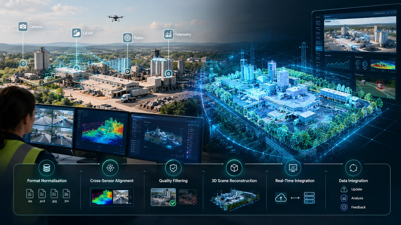
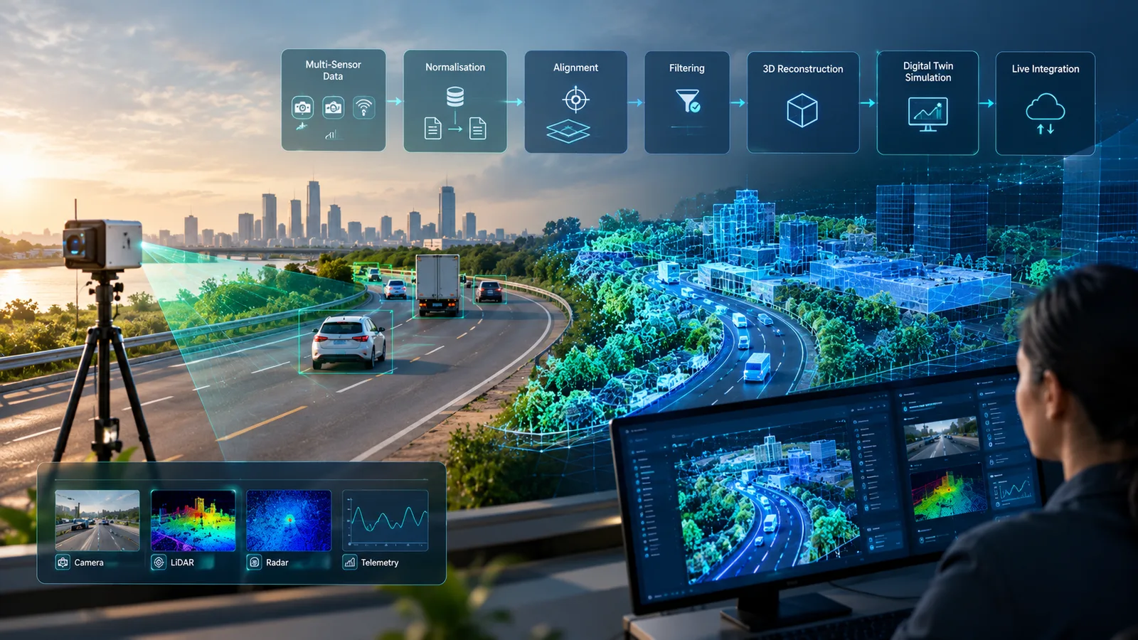
Every digital twin begins with a data collection challenge. Physical environments generate sensor data at high volume across several modalities. Cameras capture spatial geometry and surface appearance. LiDAR scanners produce dense measurements of distance and position. Radar adds velocity and obstacle detection. Telemetry records how vehicles, equipment and assets move through the space.
Each sensor type captures a different dimension of physical reality. A digital twin simulation that depends on only one modality gives an incomplete picture. It will not reflect how the environment actually behaves under operating conditions. Combining modalities is therefore not optional for serious work.
The sensor data pipeline that converts this multi-modal output into usable simulation input is where most projects hit their first serious engineering challenge. Raw data arrives in vendor-specific formats and at different sampling rates. It uses different spatial reference frames. It also has synchronisation gaps that must be resolved before digital twin data integration can begin. For organisations with mixed sensor estates, pipeline design is often the most labour-intensive part of a digital twin simulation program.
The 5 Stages of a Digital Twin Simulation Pipeline
A production sensor data pipeline follows a consistent sequence, whatever sensors are involved. Knowing the sequence helps teams separate common, reusable steps from site-specific custom work. That distinction has the biggest effect on scope and timeline estimates. The table below summarises the stages.
| Stage | Main input | Main output |
|---|---|---|
| 1. Normalise | Vendor sensor files | Standard multi-sensor format |
| 2. Align | Normalised streams | Shared time and space frame |
| 3. Filter | Aligned recordings | Usable recordings only |
| 4. Reconstruct | Filtered data | 3D scene and spatial map |
| 5. Integrate | Scene plus live feeds | Running digital twin |
Stage 1: Format Normalisation
The first stage converts raw sensor output from vendor-specific binary formats into a standard multi-sensor data format. Downstream tools can then consume data consistently. Open formats such as NCore V4 for robotics and autonomous systems data provide a normalised container. Later stages then run without a vendor-specific parser for each sensor type.
This step is a prerequisite for every later stage of digital twin data integration. It should be designed before any other pipeline component is scoped. For mixed-vendor sensor estates, normalisation is the foundational decision. It determines how maintainable the whole pipeline will be over its lifetime.
Stage 2: Cross-Sensor Alignment
The second stage synchronises data from sensors with different sampling rates and reference frames. A camera and a LiDAR scanner on the same platform record at different rates. They also sit in slightly different physical positions. Combining them requires temporal synchronisation and spatial calibration into a shared coordinate frame.
This is classic sensor fusion. Machine learning models trained on paired camera and LiDAR data now handle depth estimation, semantic segmentation and cross-sensor feature matching. At scale, these models are far more practical than manual calibration. Techniques from simultaneous localization and mapping (SLAM) also help place each frame in a consistent map.
Stage 3: Quality Filtering
The third stage removes recordings that will not reconstruct well. It runs before expensive GPU-intensive processing begins. Lighting, weather, sensor occlusion and scene complexity all affect whether a recording will succeed.
A rapid preview reconstruction processes a small sample of each recording first. It can flag problem recordings in minutes rather than hours. That prevents wasted GPU compute on inputs that will never produce a usable digital twin simulation scene. In our experience, this preview step is one of the highest-leverage cost controls in a sensor data pipeline at scale.
3D Scene Reconstruction for Digital Twin Simulation
3D scene reconstruction converts aligned, filtered sensor data into a photorealistic 3D environment. That environment becomes the visual and geometric foundation of the digital twin simulation. Modern reconstruction uses neural rendering, most commonly 3D Gaussian Splatting. It encodes geometry, appearance and lighting so the model can render views that no physical camera captured.
Gaussian Splatting represents a scene as millions of small particles. Each particle encodes position, orientation, size, colour and opacity. Reconstruction optimises these parameters against the captured images until the rendered output closely matches the photographic record. The model can then render novel viewpoints and support moving objects. That makes it suitable as the visual layer of a real-time digital twin.
Reconstruction quality matters for asset monitoring and predictive maintenance. It directly shapes how useful the digital twin simulation is for training artificial intelligence models. It also decides how well teams can test scenarios that cannot be safely replicated on the real site.
Check What the Output Package Already Contains
One discovery changes how reconstruction projects should be scoped. Many digital twin simulation projects plan a separate spatial map extraction pipeline as a major deliverable. They assume navigation data must come from custom computer vision work.
In practice, reconstruction tooling that follows the full processing pipeline often ships structured spatial map data alongside the 3D visual model. The map is part of the standard output. Finding this early removes one of the largest and least predictable scope items. Our team treats an output inventory as a required pre-build step in every scoping exercise.
Building a Real-Time Digital Twin Simulation
A 3D scene reconstruction on its own is a static visual record. A real-time digital twin adds physics, asset movement, sensor emulation and operational logic. It turns a frozen snapshot into a live, interactive system for testing, training and monitoring. The integration between the reconstruction output and a simulation engine is what makes the pipeline operational.
The architecture typically runs two parallel processes:
- Simulation engine: handles physical dynamics, asset movement, spatial logic and operating rules, usually through a physics engine.
- Rendering engine: produces photorealistic camera views from the reconstructed scene.
- Bridge layer: passes asset positions and sensor queries one way, and rendered views and readings back.
- Scaling model: each component scales independently, so GPU rendering does not block physics.
Once the reconstruction is loaded, the embedded spatial map lets the simulation engine reason about the physical environment. The digital twin simulation can then go far beyond visual replay. It can test novel asset paths, validate autonomous systems and simulate failures. For industrial asset management, this scenario testing capability is usually the main business case.
Managed platforms can host parts of this stack. Azure Digital Twins models relationships between assets and spaces. AWS IoT TwinMaker connects data sources to 3D scenes. Neither replaces a reconstruction pipeline, but both can carry the live data layer. For GPU hosting choices, see our guide to digital twin cloud deployment.
Digital Twin Data Integration: Physical Meets Digital
Digital twin data integration is the ongoing challenge that follows the initial build. A digital twin simulation that reflects the site at capture time is useful for historical analysis and scenario testing. A real-time digital twin that continuously receives live IoT data is what delivers operational monitoring, predictive maintenance and automated response.
The integration architecture must address three ongoing data flows:
- Update flow: brings new sensor readings into the twin in near real time, updating positions, condition and environmental state.
- Analysis flow: compares the current state against historical baselines to detect anomalies and predict failures.
- Feedback flow: turns decisions made in the twin into instructions for the physical environment, closing the loop.
Design all three flows before the physical sensor infrastructure is finalised. Our team recommends this because integration requirements often surface late, during operational testing. Retrofitting a feedback path into a one-way design is expensive. Industrial sources such as SCADA systems and historians usually feed the update flow, so map them early. Our article on real-time monitoring with digital twin technology covers that layer in more depth.
Scope Boundaries: What the Pipeline Does Not Deliver
Knowing what a reconstruction pipeline cannot produce is as important as knowing what it can. A single recording session reconstructs the environment as it existed at that moment. The reconstruction is a faithful capture, not an editable model. Structural changes to the site need new recordings and new reconstruction runs, not edits to old output.
Several other limits apply:
- Individual scene reconstructions do not merge automatically into one continuous environment.
- Each recording has its own local coordinate system.
- Combining scenes requires coordinate alignment, scene blending and spatial map concatenation.
- Each scene covers only the duration and extent of the original recording.
ICANIO scopes these limits explicitly in every digital twin data integration proposal. Expectations then match what current tooling can reliably produce. That honesty protects the project later, when stakeholders ask why the twin does not show last month's new mezzanine.
Digital Twin Simulation Across Industries
Digital twin programs deliver different value depending on the industry. The primary value proposition decides how the sensor data pipeline is scoped. It also sets the required 3D scene reconstruction fidelity and the priority of live integration.
| Industry | Typical use | Key data sources |
|---|---|---|
| Manufacturing | Line optimisation, maintenance | Machine telemetry, inspection |
| Logistics | Layout and route testing | RFID, cameras, WMS |
| Energy | Grid monitoring, what-if runs | Substation and asset sensors |
| Buildings | Facilities and space planning | BIM, IoT, occupancy |
Manufacturing
In manufacturing, digital twin simulation is most often used for production line optimisation and predictive maintenance. A sensor data pipeline captures machine states, throughput, quality inspection results and equipment telemetry. It feeds a real-time digital twin that models production continuously.
When a machine's readings diverge from its historical baseline, the twin can run failure prediction models against the current state. Maintenance can then be scheduled before a breakdown. This approach can help reduce unplanned downtime, depending on data quality and model maturity. Our manufacturing industry solutions page describes how this fits wider automation programs.
Logistics and Transportation
In logistics, digital twin simulation supports route planning, fleet optimisation and capacity analysis. A 3D scene reconstruction of a warehouse, combined with RFID and camera tracking, reflects real inventory locations and bottlenecks.
Teams can test new storage layouts or picking routes in the twin first. They evaluate proposed changes against real environmental data before any physical reconfiguration. Digital twin data integration with warehouse and transport management systems connects simulation output to decisions.
Energy and Utilities
In energy, the twin supports infrastructure monitoring and grid management. Pipelines aggregate readings from substations, generation assets, transmission lines and demand-side sensors. The real-time digital twin models grid state continuously.
Operators can run what-if scenarios for reconfiguration, dispatch and fault isolation. The 3D scene reconstruction adds spatial context. Field teams can locate physical assets precisely during remote monitoring and fault diagnosis.
Construction and Real Estate
In buildings, the twin supports project management, facilities management and space planning. A pipeline processes BIM models, site camera feeds, IoT readings and occupancy data. The result reflects actual building conditions rather than design-time assumptions.
Facilities managers use it to monitor HVAC performance, find energy waste and plan maintenance. They can also model how renovations would affect occupant flow and energy use. Integration with building and energy management systems creates a unified operational view.
Designing Digital Twin Simulation for the Full Lifecycle
Architecture decisions made at the start of a digital twin simulation program decide its long-term value. Pipelines built for one sensor type struggle to accept new modalities later. Normalisation standards chosen for an initial reconstruction may not support live streaming ingestion rates. One-way integration patterns cannot easily support bidirectional feedback without rework.
Our team designs pipelines and integration architectures with the full program lifecycle in mind. The goal is that the system running in year three sits on the same foundation as the one delivered in year one. That means versioned data formats, modular pipeline stages, cloud infrastructure managed through DevOps practices, and clear interfaces between reconstruction, simulation and live data.
A short checklist helps at kickoff:
- Inventory every sensor, format and sampling rate.
- Agree on a normalised format before writing parsers.
- Budget GPU time for preview runs, not only full runs.
- Document reconstruction outputs before scoping extraction work.
- Design update, analysis and feedback flows together.
For a worked example of these ideas in a vehicle context, see our vehicular health monitoring digital twin PoC.
Conclusion
Digital twin simulation is a data engineering problem before it is a graphics problem. A well-designed sensor data pipeline normalises, aligns and filters data before any reconstruction runs. 3D scene reconstruction then produces a faithful, navigable scene, often with a spatial map included.
A real-time digital twin adds physics, rendering and a bridge layer, then connects to live feeds through digital twin data integration. Honest scope boundaries keep expectations realistic. If you are planning a digital twin simulation program and want a second opinion on your pipeline, contact ICANIO to talk it through with our engineers.
References
- Digital twin, Wikipedia
- Gaussian splatting, Wikipedia
- Lidar, Wikipedia
- Sensor fusion, Wikipedia
- Simultaneous localization and mapping, Wikipedia
- Azure Digital Twins overview, Microsoft Learn
- What is AWS IoT TwinMaker, AWS documentation
Frequently asked questions
What is a digital twin simulation?
A digital twin simulation is a virtual replica of a physical environment built from real-world sensor data. It is used for testing, monitoring and analysis. It combines 3D scene reconstruction with simulation engine physics and operational logic. This enables scenario testing, predictive maintenance and autonomous system validation without any risk to the physical environment or the people working in it.
What does a sensor data pipeline do in digital twin development?
A sensor data pipeline converts raw camera, LiDAR, radar and telemetry output into a normalised, aligned and quality-filtered format. Reconstruction and simulation tools can then consume it reliably. Key stages include format normalisation, temporal and spatial alignment, quality filtering and output packaging. Together they prepare the data for digital twin data integration and long-term operation.
How does 3D scene reconstruction work?
3D scene reconstruction processes aligned sensor data through neural rendering techniques, most commonly 3D Gaussian Splatting. It encodes the geometry, appearance and lighting of a physical environment into millions of small particles. The model can then render photorealistic images from almost any camera angle. The output becomes the visual and geometric foundation of the digital twin simulation.
What is digital twin data integration?
Digital twin data integration is the architecture that connects live sensor feeds from the physical site to the digital twin. It keeps the virtual model synchronised with the current state of the asset or environment. It covers three flows: update, analysis and feedback. Together these make a real-time digital twin useful for monitoring, decision-making and closed-loop control.
What are the limits of a digital twin simulation?
A reconstruction-based digital twin simulation reflects the environment as captured during the recording session. It does not update automatically when the site changes structurally. Separate scene reconstructions also do not merge into one unified environment without extra alignment work. The honest use case is high-fidelity scenario testing and monitoring against real-world geometry, not an infinitely editable virtual model.
How long does it take to build a digital twin simulation?
Timelines depend on the number of sensor types, the size of the site and how much live integration is needed. A focused proof of concept on one area can move quickly when formats are already standard. Programs that need new sensor installation, multi-scene merging and bidirectional control take longer. Our team recommends scoping the pipeline and output inventory first, then estimating.